When a product moves from the lab bench to the production floor, in-circuit debugging with Keil and a PC per station stops scaling. What you want instead is a small box that holds the firmware, flashes boards all day, and reports pass or fail without a computer attached. That is exactly the job of the Mesilicon ME32T200 — the current-generation offline (standalone) programmer for Mesilicon MCUs.
This guide is based on the official ME32T200 application note (rev 1.1) and the Programmer 5.32 host software for Windows. It covers what the hardware does, how to load firmware into it, how to wire power correctly, and the operational details that are easy to miss until they cost you an afternoon.
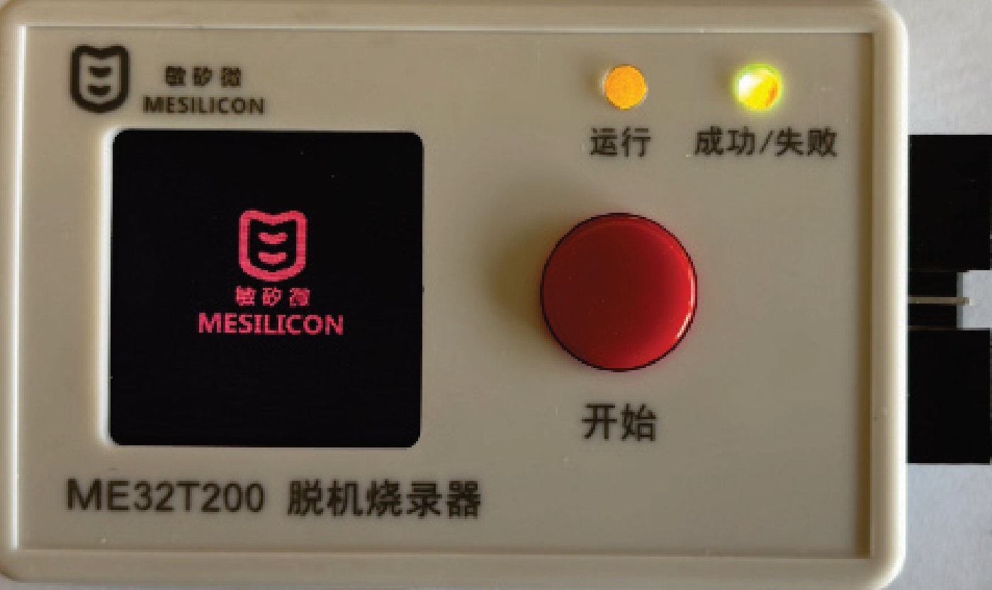
What the ME32T200 does
At its core it is a firmware vault with a flashing engine:
- 8 program slots (projects 0–7). Keep up to eight firmware images resident in the unit and switch between them from the on-device menu. Downloading a new image into an occupied slot overwrites the old one.
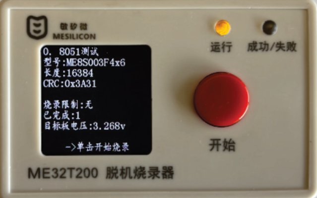
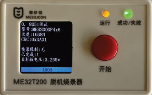
- 1.3-inch 240×240 TFT LCD. Shows the active project, target device, CRC and live burn progress — no PC required to see what is happening.
- Two target interfaces. The ARM-core parts are flashed through SWD; the 8051-core parts (ME8S series) use the M2 port. One box covers both Mesilicon families.
- Handler interface. A dedicated set of handshake signals lets an automated programming machine trigger burns and read pass/fail results — so the same unit works at a bench and inside an automated handler.
- Status output. A yellow run LED, a red/green result LED and a buzzer (short beep = pass, long beep = fail) give operators instant feedback.
The 14-pin programming connector
One 14-pin box-header connector carries both worlds: odd pins (1, 3, 5, 7, 9, 11, 13) go to the MCU target board, even pins (2, 4, 6, 8, 10, 12, 14) are the automation handler interface.
Target (MCU) side signals:
| Signal | Direction | Purpose |
|---|---|---|
| GND | — | MCU ground |
| DIO | ↔ | SWD / M2 data line |
| CLK | ↔ | SWD / M2 clock |
| DV | ↔ | MCU power, VDD/VDDA |
| RST | ↔ | MCU reset |
| B | — | MCU BOOT (reserved) |
Handler side signals (all active-low):
| Signal | Direction | Purpose |
|---|---|---|
| ST | input | Start-burn trigger from the handler |
| OK | output | Burn-success pulse when the job finishes |
| NG | output | Burn-failure pulse |
| BY | output | Busy signal while a burn is in progress |
| EV | — | Handler interface power |
| GND | — | Handler signal ground |
A note for anyone wiring this by hand: the official manual lists pin 13 both as GND and as the BOOT signal in different places — a known typo. Before you commit a cable design, verify continuity against the silkscreen on your actual unit.
The handshake timing is simple: the handler pulls ST low to start, the programmer asserts BY while working, and finally pulses OK (pass) or NG (fail).
Host software: Programmer 5.32 on Windows
The ME32T200 requires Programmer 5.3 or later — 5.32 is the current release. Three setup details matter:
- Install the CH340 driver first. The programmer enumerates as a virtual COM port through a CH340 USB-serial bridge. Without the driver, Programmer will not see the unit on any COM port. This is the single most common “software can’t find my programmer” cause.
- Connect before configuring. Programmer supports several Mesilicon
programming devices. Launch it, pick the COM port and connect — the UI adapts
itself to the detected hardware (the status bar will show
T200). - The PC connection takes priority. While Programmer is connected, the programmer will not burn target boards. Click Stop to release the unit before standalone operation.
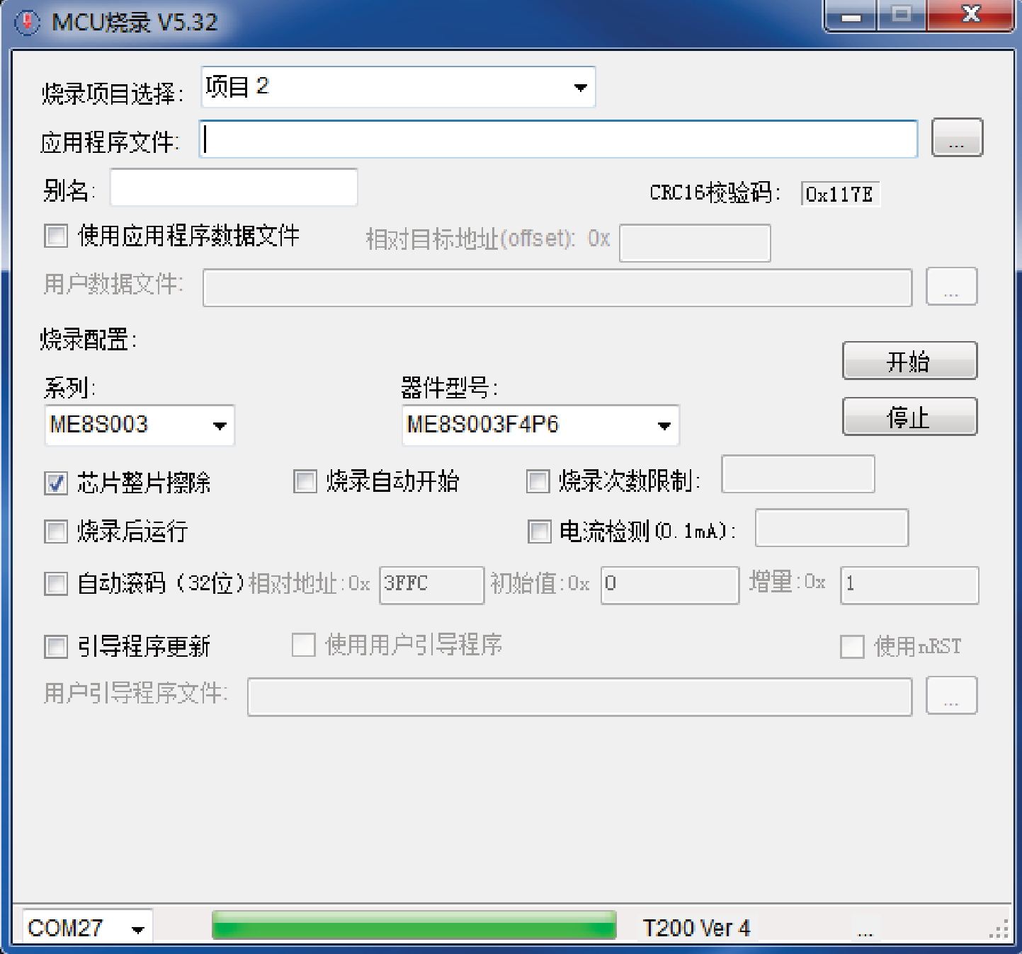
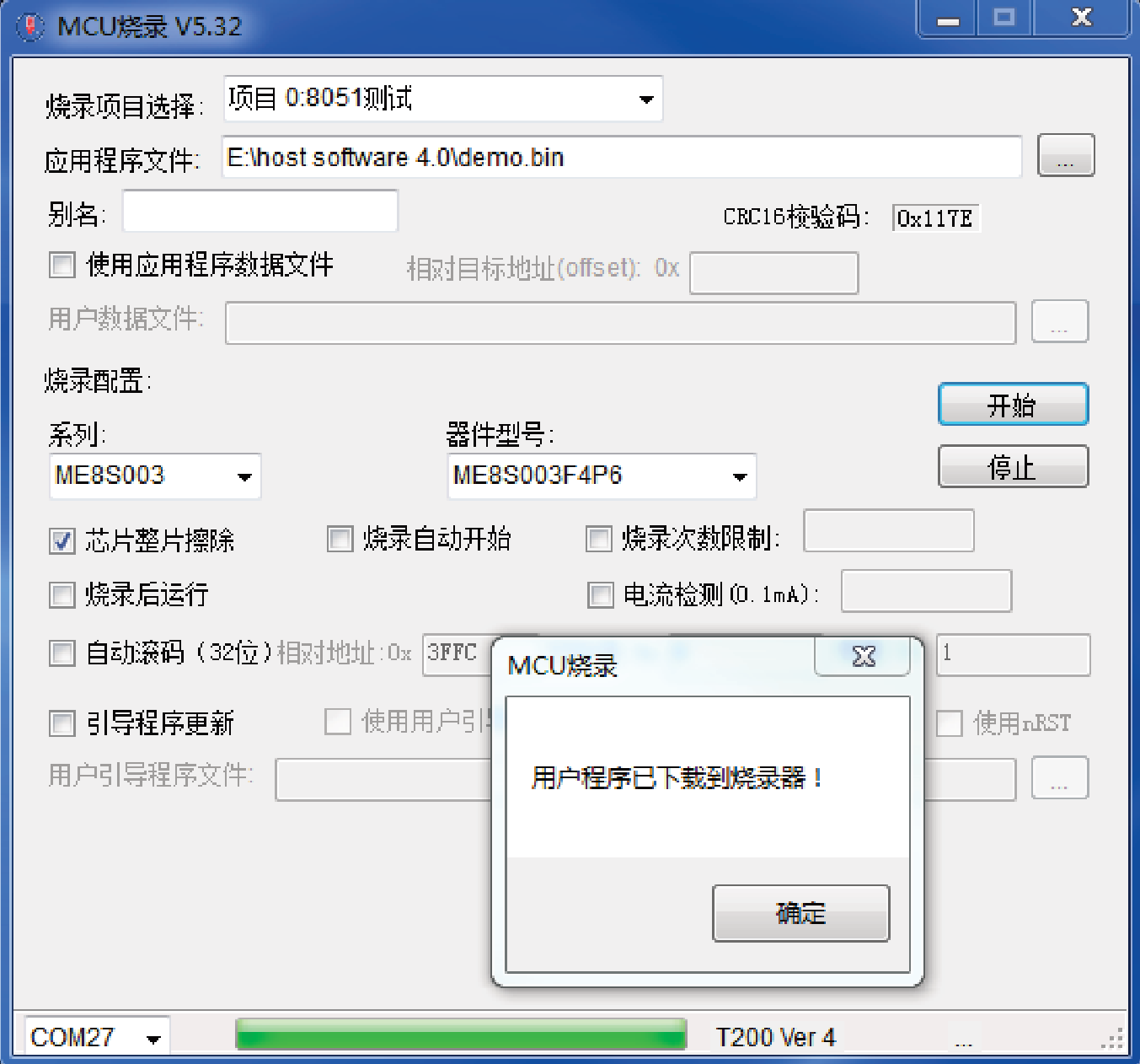
Loading firmware into the programmer
The workflow in Programmer 5.32:
- Pick a project slot (0–7). Choosing an occupied slot overwrites it — that is by design, but it is also how people accidentally lose a firmware image, so treat the slot list as production state.
- Set an alias if you like. The alias is what the LCD shows on the home screen; without one the unit displays the firmware filename. With eight slots and similar-looking filenames, a short alias like “REV2.1 MOTOR” saves real confusion on the line.
- Select the series and device (for example ME8S003 → ME8S003F4P6), then set the burn options: full-chip erase, auto-start, burn-count limit, current detection (0.1 mA resolution), run-after-burn, 32-bit auto-encryption, bootloader update.
- Click Start. The firmware downloads over the virtual COM port; the progress bar tracks it. On success you get an explicit confirmation.
- Click Stop to disconnect — only now can the unit burn targets standalone.
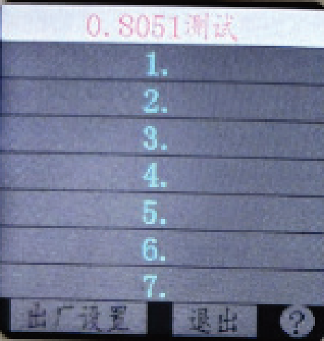
The on-device configuration menu
With no target board and no host software attached, long-press the start button to enter the configuration menu:
- Click = move to the next item; long-press = confirm.
- The menu lists projects 0–7 (the active project is highlighted in red) plus factory settings, a help page and exit.
- Long-pressing a project opens its submenu: activate it (makes it the current burn project) or delete it (wipes its data — permanent).
- Factory settings → long-press wipes all stored projects. Handle with care.
Burning a target board
In standalone operation the flow is deliberately simple:
- Connect the target through SWD (or M2 for 8051-core parts) and power it.
- The programmer auto-detects the target MCU and checks it against the project’s device setting. A match lights the yellow run LED.
- Press the start button. The LCD progress bar tracks the burn.
- Success: green LED + one short beep. Failure: red LED + one long beep.
Two rules worth taping next to the station:
- One burn per chip per session. The programmer refuses to flash the same chip in consecutive runs — re-seat or power-cycle the target between burns. This protects against double-programming a part that failed verification.
- Disconnect the PC first. As noted above, a live Programmer connection blocks standalone burning.
Getting the power wiring right
Power is where most first-day problems happen. There are three scenarios:
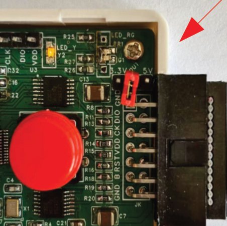
1. Target board is self-powered (most common). Power the programmer from USB Type-C (5 V). The unit draws ~120 mA active, ~10 mA with the LCD asleep. Leave the DUT jumper unpopulated — do not route the target’s voltage onto the DV pin.
2. Target board is powered by the programmer. The DV pin can supply the target: 3.3 V at up to 300 mA with short-circuit protection. Leave the DUT jumper off. If your target is a 5 V system, set the DUT jumper to the 5 V side. The 300 mA ceiling applies either way — boards drawing more than that need their own supply.
3. Target board powers the programmer. Feed the target’s voltage into DV and set the DUT jumper to match: 3.3 V target → jumper to 3.3 V; 5 V target → jumper to 5 V. A wrong jumper here is the classic way to over-voltage a 3.3 V-only MCU.
Quick reference:
| Scenario | DUT jumper | Notes |
|---|---|---|
| USB powered, target self-powered | Off | Default bench setup |
| Programmer powers a 3.3 V target | Off | DV outputs 3.3 V / 300 mA max, short-circuit protected |
| Programmer powers a 5 V target | 5 V | 300 mA max |
| Target powers the programmer (3.3 V) | 3.3 V | Match the jumper to the rail |
| Target powers the programmer (5 V) | 5 V | Match the jumper to the rail |
Firmware upgrades
Two paths:
- Automatic. When Programmer connects, it reads the unit’s firmware version and updates it automatically if it is out of date. This is the recommended path — just connect and let it do its thing.
- Manual package. The vendor firmware package contains a Keil 5 project
(no sources, but a ready
.axf) plus theme32f070.flmflash algorithm. Copy the.flminto your Keil installation’s flash folder (skip if already present), open the project and download. Reconnect Programmer afterwards and the firmware syncs up.
A pre-production checklist
Before the line starts, we recommend walking through this list once:
- CH340 driver installed; Programmer 5.32 connects and shows
T200 - Firmware images loaded into slots 0–7, aliases set, wrong slots cleared
- Correct project activated on the device (check the LCD)
- DUT jumper matches your power scenario
- Handler wiring verified: ST to trigger, OK/NG/BY to the PLC inputs
- One golden board burnt and functionally tested end-to-end
- Operators briefed: red LED / long beep → re-seat the board, never re-run
When is an offline programmer the right call?
Choose the ME32T200 when: production volume justifies a PC-free station, you need handler integration for automated programming, or the line runs several products and you want one box holding multiple firmware images. For early prototyping and firmware debugging, your existing SWD debug probe remains the right tool — the T200 earns its place at the transition into manufacturing.
We supply Mesilicon MCUs alongside the programming tools and can advise on the right burn workflow for your line — from a single T200 at a bench to a handler integrated setup. Request a quote or ask for free samples and tell us which device you are programming; we will confirm tool compatibility before you order.
Need help applying this to your design?
Ask our FAE team — free migration review, sample support and honest advice.
Contact Our Engineers